| Article ID | Journal | Published Year | Pages | File Type |
|---|---|---|---|---|
| 7047468 | Applied Thermal Engineering | 2016 | 10 Pages |
Abstract
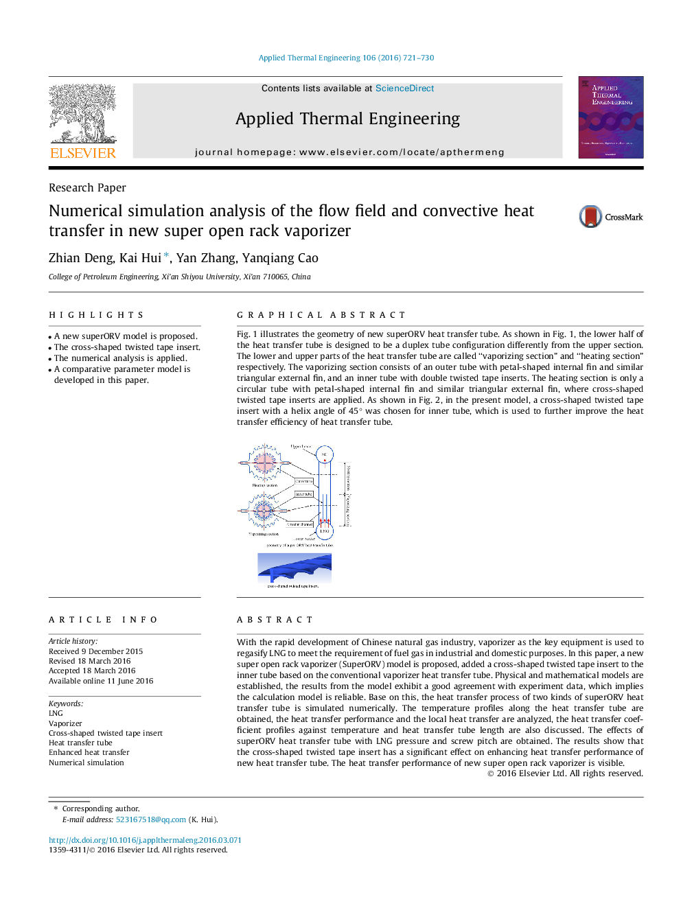
Fig. 1 illustrates the geometry of new superORV heat transfer tube. As shown in Fig. 1, the lower half of the heat transfer tube is designed to be a duplex tube configuration differently from the upper section. The lower and upper parts of the heat transfer tube are called “vaporizing section” and “heating section” respectively. The vaporizing section consists of an outer tube with petal-shaped internal fin and similar triangular external fin, and an inner tube with double twisted tape inserts. The heating section is only a circular tube with petal-shaped internal fin and similar triangular external fin, where cross-shaped twisted tape inserts are applied. As shown in Fig. 2, in the present model, a cross-shaped twisted tape insert with a helix angle of 45° was chosen for inner tube, which is used to further improve the heat transfer efficiency of heat transfer tube.174
Related Topics
Physical Sciences and Engineering
Chemical Engineering
Fluid Flow and Transfer Processes
Authors
Zhian Deng, Kai Hui, Yan Zhang, Yanqiang Cao,
